6.2. Cross-Section Behaviour {General, Material Non-Linear} [CALSNLN]

Contents
Perform cross-section calculations (material non-linear analysis)
General description:
Through this design function deformations, stresses and strains are calculated in specified cross-sections of the pipeline. Cross-sections are located at the mid-sections of elements.
Function description:
The function calculates the deformations and stresses in specified cross-sections and max/min results are stored in the output data tables. One data line per cross-section specified. Detailed data over the circumference of the cross-section are contained in the additional output data tables. These tables only contain results of the last cross-section calculated. At the start of a new cross-section the additional output data tables are cleared and during the calculations on the new cross-section filled with the detailed data of that new section. If detailed data are required from each cross-section to be analysed, it is advised to perform this sub-function separately for each cross-section using the 'unlock'-functionality of this sub-function.
Overall results of previous calculations are accumulated in the output data tables of this sub-function until this function is set back. In that case all output data tables are cleared.
Additional output data tables:
The additional output data tables are filled with detailed deformation and stress data concerning a mid-section of an element. Through these additional output data tables, detailed information on the behaviour of a cross-section can be obtained.
As the number of detailed data on a cross-section is quite substantial the detailed data per cross-section is not stored in the database. Results of calculations on a new cross-section overwrite the results of previous calculations. Hence, if a list of cross-sections has to be calculated, only the detailed data of the last cross-section will be available through the additional output data tables.
In case the designer wants to have available all detailed data per cross-section, the function can be performed with one cross-section at the time.
The unlock facility (refer to the overview panel help screen for more details) allows you to restart the calculation process from the last element calculation performed. This feature is especially useful when multiple cross-sections need to be analysed. When you use the unlock facility, the calculation results for the specified cross-sections in this table are added to the output data tables of this function.
After unlocking, the input tables in Design Function 6.2 can be modified. This means you can change the SECTION table to select which cross-section to calculate (next). This functionality enables you to perform a series of calculations on completely different parts of the pipeline.
If the SECTION table includes a cross-section that already has results stored in the output data tables, this cross-section will not be recalculated. However, the last cross-section specified in the SECTION table will always be calculated to obtain detailed stress results, unless it is the same as the last calculated cross-section.
When you use the unlock facility and subsequently perform a calculation for this Design Function:
•the results for the specified cross-sections in this table are added to the output data tables of this Design Function
•if the SECTION table includes a cross-section that already has results stored in the output data tables, this cross-section will not be recalculated. However, the last cross-section specified in the SECTION table will always be calculated to obtain detailed stress results, unless it is the same as the last calculated cross-section.
When setting back a locked design function, the result data in the output tables will be cleared and replaced by new calculation data. Unlocking, on the other hand, leaves previous calculation data in the output tables intact (does not clear it) and adds the new calculation data into the output tables.
![]() Unlock facility is available for specific functions only: Design Function 5 and Design Function 6.2.
Unlock facility is available for specific functions only: Design Function 5 and Design Function 6.2.
![]() Any design function following the unlocked function is set-back!
Any design function following the unlocked function is set-back!
How to's:
Using the input table SECTION, one or more sections can be specified by indicating the start and end points of each section. Examples of defined sections are shown below. Each section has additional loads on top of the soil and allowable stress value of 565 N/mm2. Section with multiple elements Stress and strain calculations will be performed on multiple elements within a defined range of the pipeline. 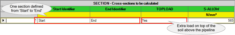 Section with one element only If no section is desired, it is sufficient to specify only the start point as the beginning of the section. The end of the section can be left blank. This also means that the stress and strain calculation will only be done for the element at the given starting point. 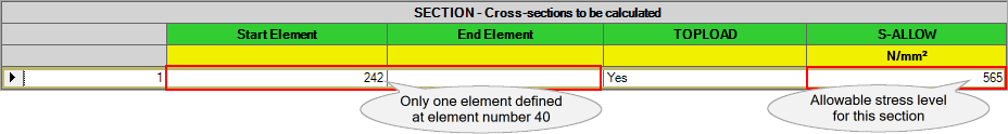 Combination of sections Combination of both section with multiple elements and a single element is also possible. 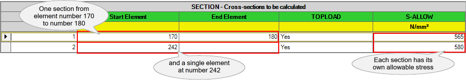 |
The results of the stress and strain calculations contained in the output tables depend on the specified sections in this table SECTION. Only the calculation results for these sections are displayed in the output tables. Section with multiple elements 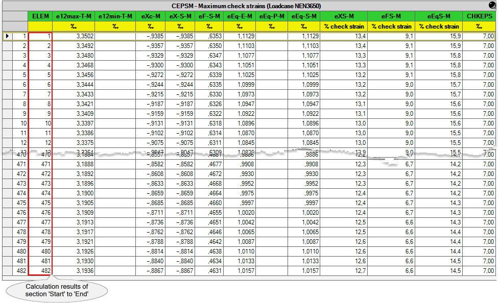 Section with one element only  Combination of sections 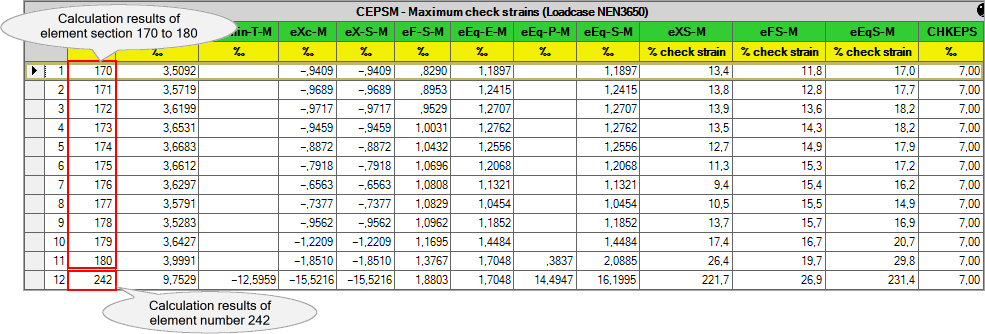
|
Detailed stress and strain calculation results can be found in the additional output tables. The additional output tables contain various detailed stresses and strains over the circumference of the cross-section where calculations have been performed. The stresses and strains are given in 144 equidistant points over the circumference of the cross-section (each 2.5°) starting at the intersection of the horizontal y-axis of the element coordinate system and the cross-section. Please note that the detailed calculation results shown in these tables are only of one specific cross-section (element). This specific cross-section of interest is automatically taken by PLE if the cross-section is the last cross-section specified in this SECTION table. Or, in other words: •The cross-section is, in the absence of an end point, the start point of the last defined section in the SECTION table, or 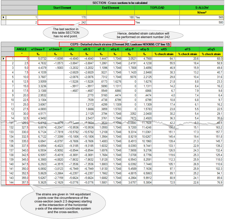
•The cross-section is the end point of the last defined section in the SECTION table. 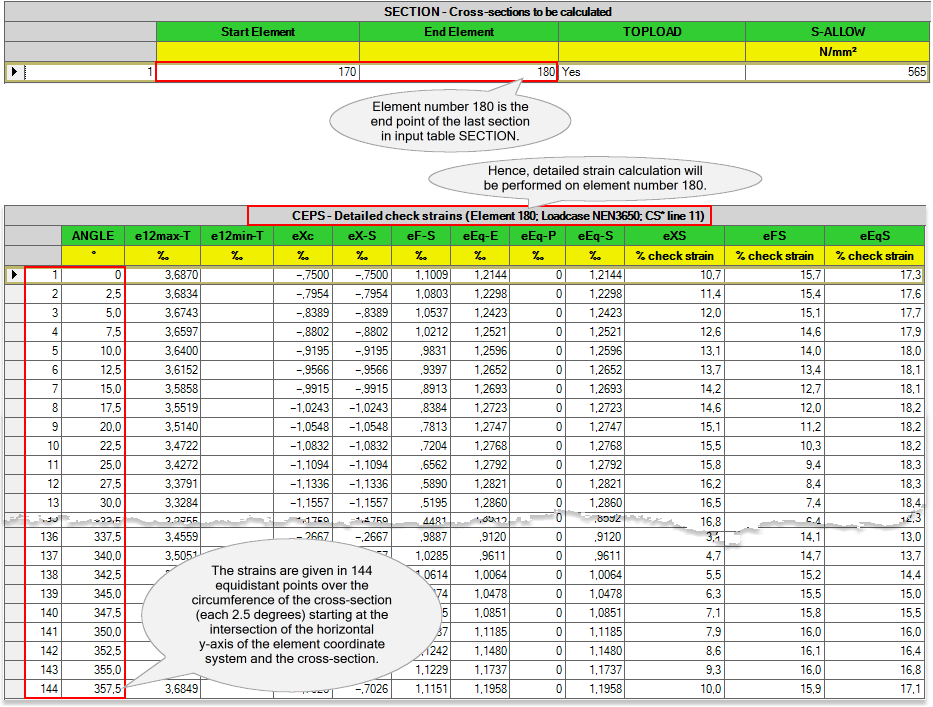
|
Sometimes, the data status of this Design Function may show a warning or an error. You can identify this by looking for a yellow dot with a red lower half in the Roadmap panel. If you see this half yellow-red dot, open the specific Design Function to check the data status of each table associated with this Design Function. For example, in this case, the output tables RLDPLMX and CEPSM has locked data with a warning, indicated by a red-shaded dot. This warning usually relates to the maximum calculated strain being greater than the check/critical strain. If this check/critical strain is exceeded, this warning will be displayed.
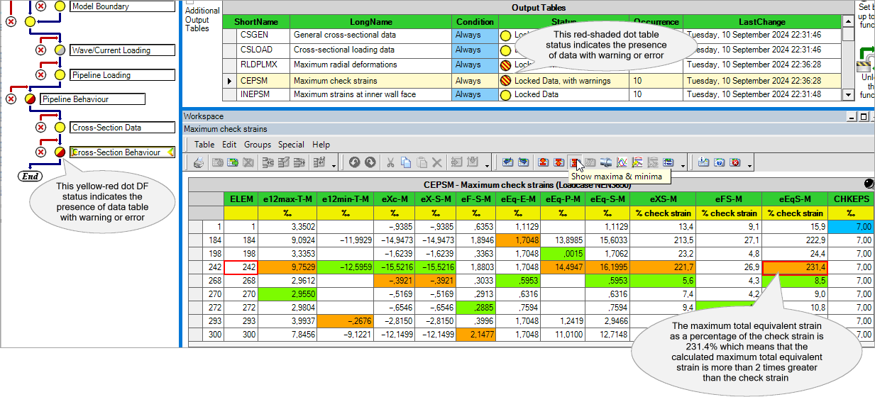
This also applies to the additional output tables. If any of the calculated strains exceed the check strain, a red-shaded warning status will be given. In the example above, the highest total equivalent strain is observed in element number 242. To gain a clearer understanding of the circumferential strain distribution across this element's cross-section, element number 242 has been designated as the cross-section of interest. The detailed calculation results are shown below. 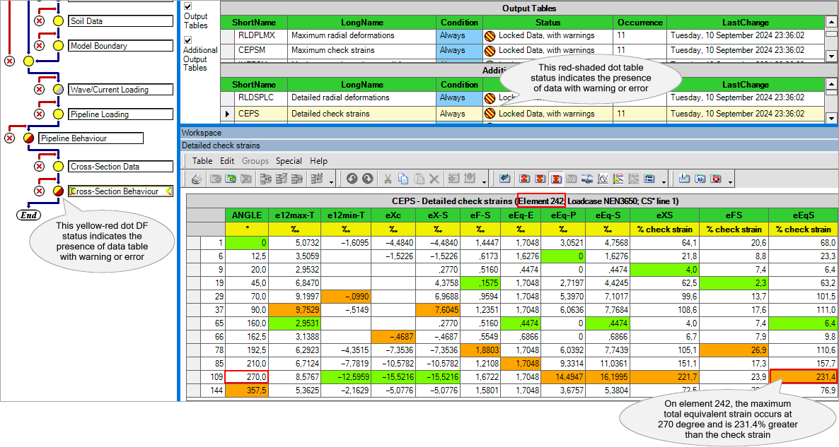
|
H6223 (last modified: Sep 23, 2025)
See also: